TPWC315 BAND SAW OPERATION MANUAL

Guarantee Clauses 1. The guarantee range refers to the whole machine. 2. Maintenance for malfunctions during normal utilization is free of charge within guarantee time that is 12 months 3. The guarantee time starts with the date of delivery. 4. Fees are charged in case of the following condition: 4.1 Malfunction caused by improper operation 4.2 Damages caused by fire, flood, and abnormal voltage 4.3 Working exceeds its normal function 5. Fees are charged as actual expense. A contract about the fees shall be abided if there is one. 6. Please contact us or our agent if any questions.

Products Details

Before operating the machine, anyone must read this description carefully and keep it well to ensure the equipment and operator’s safety, as well as others’ safety. 2.1 This machine is used to cut pipes made from PE, PP and PVDF and can not be used to cut no-description materials; otherwise the machine may be damaged or result in accident. 2.2 Don’t use the machine in a place with potential hazard of explosion 2.3The machine should be operated by responsible, qualified and trained personnel. 2.4The machine should be operated on a dry area. The protective measures should be adopted when it is used in rain or on wet ground. 2.5 The input power is within 380V±10%, 50 Hz. If extended input line is used, the line must have enough lead section. 2.6 Fill hydraulic oil (N46 ISO3448) into tank before the first time using. The oil volume should be about 2/3 of the tank.
 
The following marks are affixed to the machine.
 
Caution, danger! Please caution when work or close to area with this sign!  SDC315 Band saw Operation Manual (1)
Danger, electrical shock! Parts with this sign may have a danger of electricity leak.Be careful when working here.  SDC315 Band saw Operation Manual (2)
Caution, injure hand  SDC315 Band saw Operation Manual (3)
 
3.2. Precautions for Safety When operating the machine, instruction and safety rules should be abided carefully. 3.2.1 The operator should be trained and skillful personnel. 3.2.2 Completely inspect and maintain the machine per year for the safety and machine’s reliability. 3.2.3 Power: the electricity distribution box should have ground fault interrupter with relevant electricity safety standard. Earthing: The whole site should share the same ground wire and the ground connection system should be finished and tested by professional people. 3.2.4 Storage of the machine: For the min dangers all equipment must be operated as follows: ※ Do not touch electrophorus parts ※ Forbid hauling off the cable to disconnect ※ Do not put heavy or sharp object on the cables, and control the temperature of cable within limiting temperature (70℃) ※ Do not work in the wet environment. Check if the groove and shoes is dry. ※ Do not splash the machine 3.2.5 Check insulation condition of machine periodically ※ Check the insulation of cables specially the points extruded ※ Do not operate the machine under extreme condition. ※ Check if the ground fault interrupter works well at least per month. ※ Check the earthing of the machine by qualified personnel 3.2.6 Clean the machine carefully ※Do not use materials damaging the insulation easily (like gas, abrasive, and other solvents) ※The power should be disconnected when finishing job. If only following above mentioned, the precaution can work well. 3.2.7 EMERGENCY STOP Any unexpected status occurs, please press “EMERGENCY STOP “immediately to stop the machine. After solving problems turn EMERGENCY STOP clockwise to start machine again. 3.2.8 Tightness of parts: Check if the pipes are fixed correctly and tightly. Make sure that it can not slide down to injury operator 3.2.9 Personnel safety while working Remove jewelry and rings, and does not wear loose-fitting clothing avoid wearing shoe lace, long mustache or long hair that may be hooked into the machine.
 
3.2.10 Keep the site clean and tidy Crowd, dirty and mussy site is not favourable to working, so it is important to keep the site clean and tidy. 3.2.11 Untrained person should never be allowed to operate the machine anytime. 3.3 Potential Dangers 3.3.1 Band saw This machine is only operated by professional person or trained personnel, otherwise unwanted accident maybe caused. 3.3.2 Saw Blade Never touch the running saw blade, or injury may cause 3.3.3 Cutting Before cutting, clean the sand outside of the pipes or other draff crowed in the pipes when transporting. This can avoid unwanted damage of the saw blade or other accidents


Type

TPWC-315

Materials for cutting

PE,PP, PVDF

Max. Cutting capacity

315mm

Cutting angle

0°~67.5°

Inaccuracy of angle

≤1°

Line velocity of saw blade

230 m/min

Environment temperature

-5~45℃

Power supply

~380 V±10 %

Frequency

50 Hz

Total current

5A

Total power

3.7 KW

Driving Motor

2.2 KW

Hydraulic unit motor

1.5 KW

Insulation resistance

>1MΩ

Max. hydraulic pressure

6 MPa

Total weight (kg)

1100

 
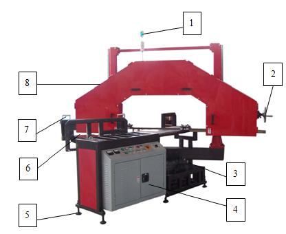
The band saw can be used to cut PE pipes according to set angle when making elbow, tee and cross, so that the machine has features of high working efficiency and utilization rate of materials. 5.1 Description of the parts
SDC315 Band saw Operation Manual (9)

1. warning device

2. tension wheel

3.angle scale

4. control box

5. level adjustor

6. 67.5° seat

7. fix device

8.saw box

5.2 Operation panel
SDC315 Band saw Operation Manual (10)
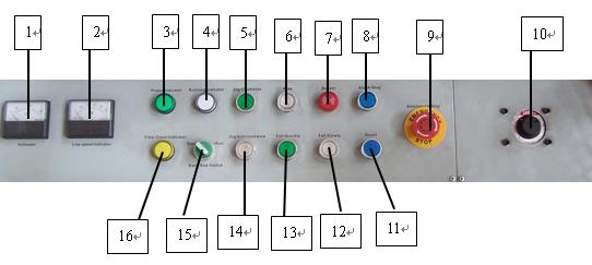
1. Voltmeter 2. Line Speed Indicator 3. power indicator 4. Running indicator
5. Jog clockwise 6. Rise 7. Buzzer 8. Alarm stop
9. Emergency stop 10.Feed speed adjustor 11. Reset 12. Fall slowly
13. Fall quickly 14. jog anti clockwise 15. Band saw switch 16. oil pump working indicator
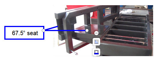
6.1 Lifting and installation 6.1.1 If a forklift is used while installation, insert the fork carefully from the bottom of the machine to avoid damaging the oil hose or circuit. 6.1.2 When placing the machine, the machine should be kept stable and level by adjusting the level adjustor 6.1.3 This standard machine can cut angle 0~67.5°, if an angle within 45° is required, the 67.5° seat should be removed before working
7.1 Starting 7.1.1 Power the machine, and the power indicator must be on (if not on, the connection is wrong). 7.2 Testing of the saw box moving up and down by turning the feed speed adjustor on the right of operation panel. 7.3 Press the “jog clockwise” and “jog anticlockwise button “to check the running direction of the saw blade. If it rotates in the wrong direction, exchange connection between any two live wires linked to the power supply. 7.4 Cutting operation 7.4.1 Loosen the angle locking screw, push the saw blade box by hands to required angle (as per the required angle), and fasten the angle locking screw. 7.4.2 Raise saw blade box to a height (determined by the diameter of pipe to be cut) to ensure the saw tooth is above the pipes. 7.4.3 Put the cutting tubing on the work table, adjust the cutting position, and fix the pipe with nylon belt by locking device. 7.4.4 Start the saw blade, when the saw blade achieves specified speed (Running indicator will shine), turn the feed speed adjustor to fall the saw box slowly. The speed of falling should be regulated according to the pipe diameter and thickness. 7.4.5 When the cutting is going to be finished, please hold the pipe cut down to avoid blocking the saw blade. 7.4.6 Press emergency button if any abnormity occurs during cutting. After solving problems turn EMERGENCY STOP clockwise to start machine again.. 7.4.7 Saw blade will stop automatically when it reaches lower limiting position 7.4. 8 When finishing the cutting Remove the cut pipe and recut. 7.4. 9 This standard machine can cut angle 0~67.5°, if an angle within 45° is required, the 67.5° seat should be removed before working on the pipes, shown as follows:
SDC315 Band saw Operation Manual (11)
Caution: 1) Power the machine again in 30 minutes after cutting off the power to protect the converter. 2) The whole machine must be earthed to ensure safety 3) The check and maintenance of the electrical components must be done by professional person
Please use tools attached, spare parts or other tools with a safety certificate while maintain or replace parts. Tools and spare parts without safety certificate are forbidden to be used. Table.1 Mechanical failure

Item

Description

Analysis

Solutions

1

Band saw blade

is jammed

1. The angle of rotary seat is not locked tightly.  2. Band saw blade is not tensioned tightly. 3. The saw blade run too slowly or the saw blade fall down too quickly 1. Fasten the angle locking device.  2. Regulate the tension roller to tension the band saw blade. 3. Lower down the falling speed and adjust high the line velocity of saw blade.

2

Band saw blade

drops

1. Saw blade holders have not been adjusted well.  2. Band saw blade is not tensioned. 3. Saw blade wheel is loosened. 4. The core of overflow valve is blocked 1. Adjust the saw blade holder to fix the band saw blade in optimum position.  2. Adjust the tension roller to tension the band saw blade. 3. Fasten the saw blade wheel tightly. 4. clean the core of the overflow valve
Table.2 Hydraulic system faults

Item

Description

Causes

Solutions

1

The motor of oil pump does not work 1. Contactor is not closed  2. Internal lines are disconnected 3. The motor is fault. 1. Check the contactor;  2. Check the connection or plug. 3. Inspect and repair the motor.

2

No pressure in system, and loud noise in pump 1. Rotation direction of oil pump motor is not correct;  2. Coupler of motor and oil pump is disconnected 3. Oil is insufficient or too dirty. 1. It should rotate counterclockwise;  2. Check the coupler; 3. Fill or change the oil;

3

Lifting speed of main cylinder is too quick or too slow 1. System pressure is too high or low;  2. Throttle valve is adjusted improperly; 3. Controllable cheek valve is adjusted improperly. 1. Adjust the system pressure;  2. Adjust the throttle valve; 3. Adjust the single direction valve.

4

Pressure cannot be adjusted to higher or pressure fluctuation is too large 1. The overflow valve core is blocked  2. Oil filter is blocked. 3. Overflow valve core is blocked 1. Disconnect & wash or change the overflow valve  2. Wash the oil filter. 3 .Disassemble and clean the overflow valve core.
9.1 Circuit unit diagram (Reference to appendix) 9.2 Hydraulic unit diagram (Reference to appendix)

Contact us

Please feel free to give your inquiry in the form below We will reply you in 24 hours